2P Innovation · free, no sign-up
Distributed-element geometry synthesiser
Choose a topology and generate CAD you can use: a KiCad footprint, a DXF, dimensions and a layout to scale. Every design is checked against six fabricators' published limits before you order the board.
Edge-coupled bandpass filter
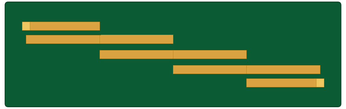
Parallel-coupled half-wave resonators. The classic microstrip bandpass.
validated Response validated against published data
Notes
- Spurious at 2f0. Plan a lowpass after it if the second harmonic matters.
- Below roughly 5% FBW the first gap drops under 0.1 mm. Check the fab panel before ordering, not after.
- At 1 GHz this stops being a sensible shape. Go hairpin or interdigital.
- The one to reach for when you want the answer to be right rather than small.
Hairpin bandpass filter

Edge-coupled resonators folded into hairpins.
unconfirmed Closed form not yet confirmed against full-wave EM
Notes
- Folding couples the two arms of each resonator and the equivalent edge-coupled model does not see it. Expect f0 to land low.
- Simulate before committing. This is the only topology here whose response has not been checked against EM.
- The tapped feed puts the tightest feature inside the array rather than at the port, which is usually what you want.
- Buys length, spends width. Not a smaller part, a differently shaped one.
Interdigital bandpass filter
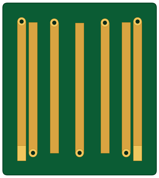
Quarter-wave bars grounded at alternating ends.
indicative Response is indicative, geometry is the deliverable
Notes
- First spurious near 3f0 rather than 2f0. The clean window above the passband is much wider than either half-wave filter gives you.
- Via inductance is not in the model, and the bar-to-ground transition is a fab detail this tool cannot check.
- Of the three filters, the one most worth an EM run before you commit copper.
- Bars side by side suit a narrow board, which is often the deciding factor.
Wilkinson power divider

Two-way split with matched ports and isolation between the outputs, set by a single bridging resistor.
validated Well-behaved closed form
Notes
- Isolation is set by the resistor's placement and its parasitic inductance, not by its value. At these frequencies the mounting matters more than the part.
- Unequal splits work as readily as equal ones.
- Past about 30% go multi-section. A single section will not hold both match and isolation.
- The only part here that is not purely copper.
Branch-line coupler

Quadrature hybrid: an equal split with 90° between the outputs. Four quarter-wave arms in a ring.
validated Well-behaved closed form
Notes
- Series arms run at Z0 over root two, about 35 ohm, so they come out wide. The area goes up fast as frequency comes down.
- Four junctions, all treated as ideal. Compensating them is an EM job.
- 90 degrees between the outputs is the whole point: balanced amplifiers, I/Q mixers.
- Split ratio and phase both drift outside the band. It degrades gracefully, but it does degrade.
Things to note before using this tool
- Fabrication. Geometry is checked against six shops' published limits. If it cannot be built, you are told, and by whom it can be.
- Loss. There is no dissipation model. Every response is lossless and peaks at 0.000 dB. Insertion loss is not something this tool knows.
- Models. Every closed form is cited with the range it is valid over. Outside that range the engine warns rather than extrapolating quietly.
- Substrates. Permittivities are datasheet design values, not IPC process values. On a 4.75 GHz hairpin that is about 95 MHz of centre frequency.
- Confidence. Each topology states how far its response has actually been verified. They are not all the same.
- Scope. Closed-form synthesis, not simulation. Verify in EM before you fabricate.
Coming soon, maybe
- Coupled-line directional coupler. Built, but its directivity is an unverified prediction, and directivity is the only number that decides whether the part is usable.
- Radial / butterfly stub. Not built. The curved-geometry primitive is done; the synthesis is not.
2P's own rule for the engine is that if a capability is not built and functional, it is not claimed. The website inherits that rule.
Want a design verified full-wave?
Closed-form synthesis is a starting point, not a guarantee. Send us a design and we will run it through a full-wave EM solve and come back with the S-parameters and an engineer's read on what they mean.
Ask for an EM verification →These get built in Australia.
2P Innovation designs, fabricates and assembles RF hardware locally, to Class 3, fully documented.
About 2P Innovation →